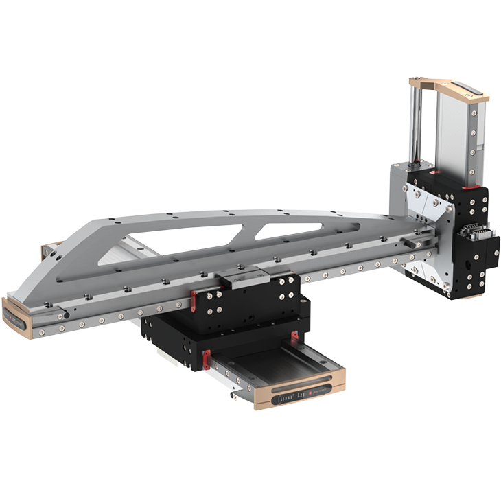
X-y-z pick and place
Y-Z Pick and Place arrangements can be easily extended to the third dimension X. The Y-axis is screwed in right-angled orientation directly onto the X-axis. Thanks to the modular system, the corresponding holes, threads and centering pins already exist. Thanks to the selectable lengths of the individual axes, the installation volume can be kept very compact, compared to robots.
Furthermore, it is possible to arrange the X-axis “overhead”, then the mounting plate on the bottom remains completely free for parts handling with feed and removal from all directions.
Front flange
With the front flange it is possible to mount different Pick and Place orientations: The front plate of a LINAX® Lxu is replaced by the front flange which can directly be mounted to:
- An ELAX electric slide (upright or flat),
- A linear motor axes LINAX® Lxc F08/F10 or F40
- Or to the carriage slider of another linear motor axes LINAX® Lxu
Front flange LINAX® Lxu linear motor axes
| Front flange LINAX® Lxu | Accessories | Art. No. |
|---|---|---|
| For ELAX® Ex F20 upright | incl. 2 centering pins 4x8, 6 torx M4x8 and 2 dowel bushings D7 |
135.12.02. |
| For ELAX® Ex F20 flat | incl. 2 centering pins 4x8, 4 torx M4x8, 4 hexagon socket screws M3x30 and 4 dowel bushings D6 |
135.12.03 |
| For Lxu | incl. 2 centering pins 4x8, 4 torx M4x12, 4 centering pins 2.5x5 and 8 torx M4x8 |
135.12.05 |
| For Lxc F40 | incl. 2 centering pins 4x8, 4 torx M4x12, 4 centering pins 2.5x5 and 4 hexagon socket screws M3x35 |
135.12.06 |
| For Lxc F08/F10 | incl. 6 centering pins 4x8, 8 torx M4x8 and 4 torx M4x12 | 135.12.07 |
Download files modular construction LINAX®, ELAX®, ROTAX®
| CAD-FILES_STEP_FLANGE_ADAPTER_PLATE_BRACKET.zip – Login |